
TESCAN, with a rich history spanning 30 years, has been a pioneer in the SEM and FIB-SEM market. The expansion into Micro CT technology was supported by the strategic acquisition of XRE in 2018, a dynamic spin-off from the University of Ghent’s Center for X-ray Tomography (UGCHT) in Belgium.
The Micro CT product range from TESCAN stands out for its versatility and ability to accommodate diverse sample sizes. A key feature is the Dynamic CT capability, made possible by our ultra-rapid scanning processes. This breakthrough allows for in situ experimental imaging, enabling ongoing experiments to be captured in near real-time as events occur.

TESCAN offers three Micro CT systems to meet specific research needs:
CoreTOM: This system features a fixed detector with a rotating sample mechanism, ideal for standard imaging requirements.
DynaTOM: A standout in the realm of non-medical CT imaging, this gantry-based system allows both the source and detector to orbit the stationary sample, offering unparalleled imaging perspectives.
UniTOM XL: Tailored for high-throughput environments, this system maintains a fixed detector while the sample rotates, accommodating a wide array of sample types and providing the adaptability needed for various research applications.
The Evolution of Computed Tomography
X-rays, a distinct type of electromagnetic radiation, are invaluable in imaging due to their ability to penetrate substances and unveil internal structures. The origin of X-rays dates back to German physicist Wilhelm Röntgen (1845-1923), who discovered their emission while experimenting with a Crookes-Hittorf tube. He called them “X” rays for their mysterious properties, they are also known as Röntgen Rays in honour of their discoverer. By 1900, a mere five years post-discovery, X-rays had already become a staple in medicine for internal imaging.
Fast forward to the present, X-rays have transcended their medical origins to become instrumental in fields such as materials science, security, and food safety. The 1960s marked a crucial moment when Godfrey Hounsfield, a researcher at EMI, pioneered the first computer-assisted X-ray system. Interestingly, EMI’s venture into the music industry, particularly their success with The Beatles, provided the financial backing for Hounsfield’s groundbreaking research, culminating in the advent of the first CT scanner. His monumental contribution to medicine was later recognized with the Nobel Prize in 1979.
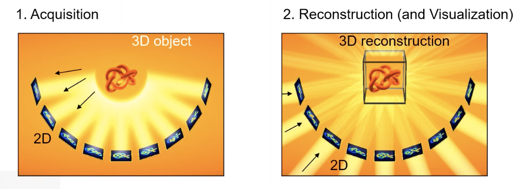
Computerized Tomography Fundamental Concepts:
A series of 2D radiographs are collected in the acquisition phase, and these images are projected to create a 3D reconstructed visualization.
In the early 1980s, the first microCT system was developed to allow pixel sizes around 50 microns. Today, submicron resolutions are supported by commercial systems.
Basics of micro-CT imaging
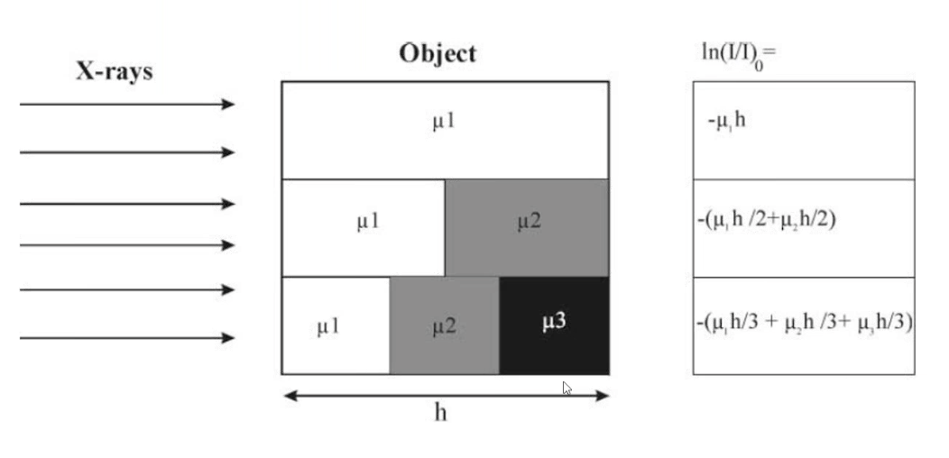
The intensity of the signal detected in each two-dimensional pixel correlates with the material’s chemical composition and the X-ray’s traversal distance through it.

For specimens composed of multiple materials, the signal’s absorption or intensity is the cumulative result of the X-ray’s interaction with each material.
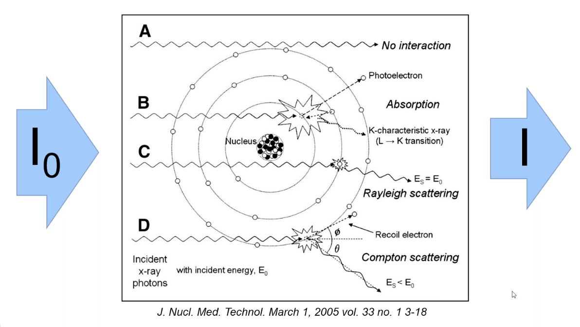
On the atomic scale, X-rays undergo three primary interactions with atoms: photoelectron absorption and Compton scattering, which are instrumental in generating CT images, and Rayleigh scattering, which is more pertinent to diffraction imaging techniques.
The attenuation of the X-ray signal depends on the atomic composition of the sample. As the atomic weight increases, the required signal strength to penetrate an equivalent path length increases by the power of three.

A diverse array of metals serves as sources for X-ray emissions, each yielding distinct narrowband and broadband emission spectra. Consequently, each different source type creates a unique interaction profile with the target material.
The system’s resolution is determined by an interplay of factors: the X-ray spot size (s), the detector’s resolution (d) - encompassing size and pixel count, and the geometric magnification (M), which depends on the sample’s positioning relative to the detector and the source.
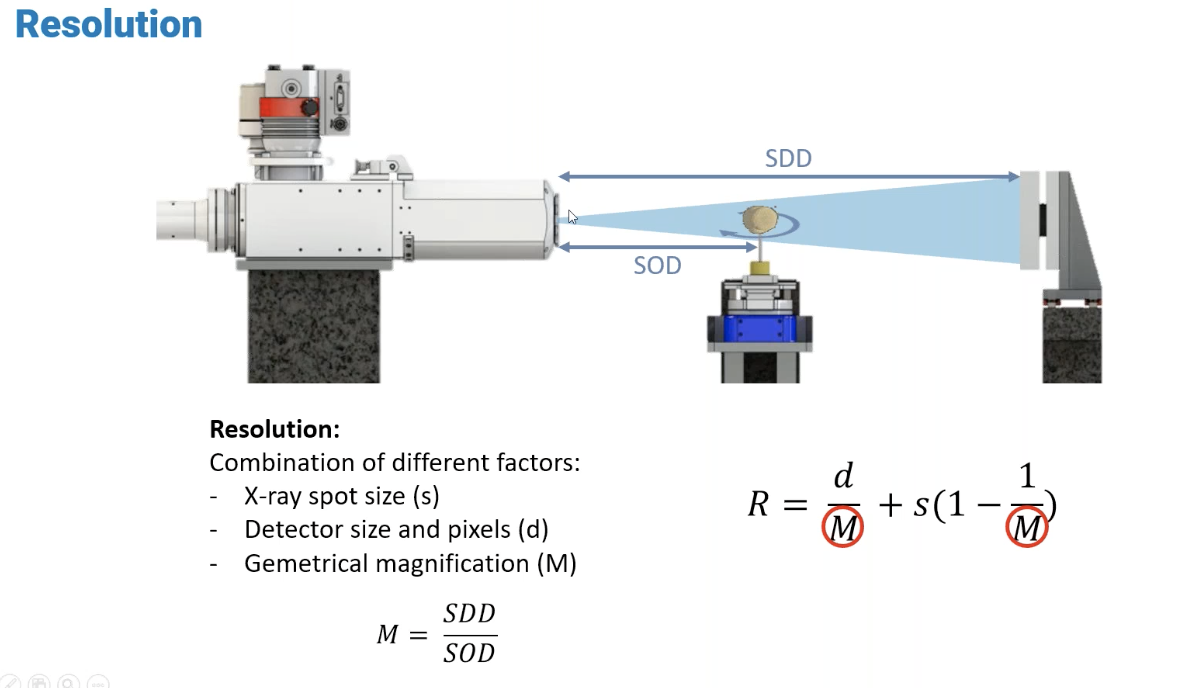
When a sample is positioned very close to the detector, the resulting magnification is minimal. Conversely, a sample situated near the source undergoes significant magnification.
The reconstruction of sample slices post 2D image collection involves processing numerous projections via a Radon transform. Subsequently, a filtered back-projection technique is employed to compile a stack of sliced images.

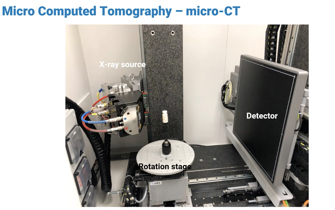
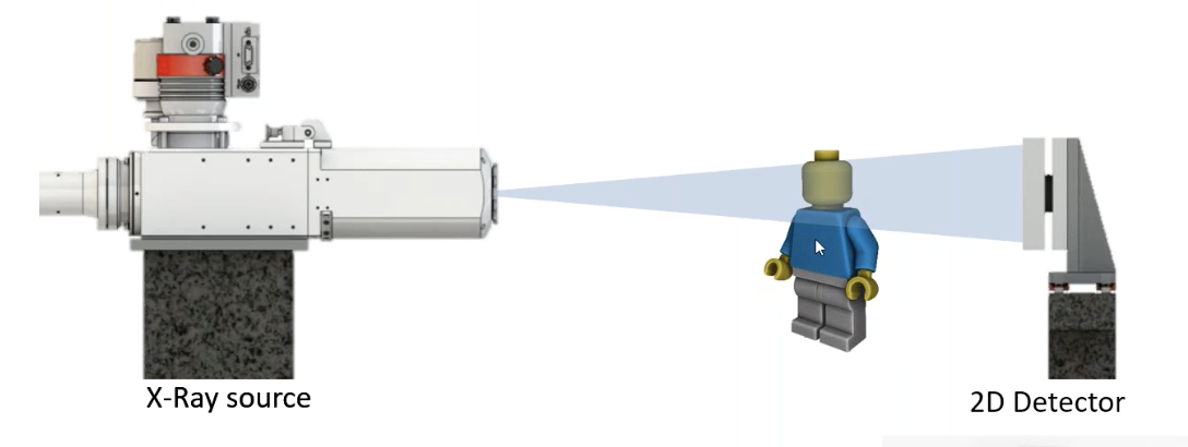
The Micro CT system’s core elements consist of the X-Ray Source, Detector, and Rotation Stage, each playing a pivotal role in the imaging process.
Micro CT utilizes two principal types of X-ray sources.
Reflection X-Ray Source: This high-power source is adept at penetrating dense materials. However, the larger spot size inherent to these systems yields a lower resolution. Additionally, the distance of the reflection spot from the window influences the system’s maximum achievable magnification.

Transmission X-Ray Source: This is utilized for achieving higher resolution imaging due to its small focal spot. The target material, with a thickness ranging from 1 to 10 micrometers, is mounted directly onto the window. This proximity to the window facilitates increased magnification capabilities.

As the resolution of the spot increases, the power of the system decreases, necessitating a smaller sample size, particularly for dense samples. To achieve higher resolution images, extended scan times are required.
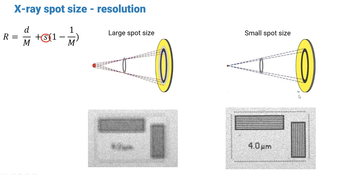
The accompanying diagram illustrates the relationship between spot size and resolution. A larger spot size allows photons to originate from a broader area, resulting in a bluer tint on the detector. Despite both images having identical detector resolutions, this demonstrates the significance of spot size alongside voxel dimensions in determining the system’s overall resolution.
The detector employs a scintillating material that transforms photons into visible light. This light then strikes a photodiode, causing an electron flow within the diode matrix that is subsequently quantified.


The diagram above demonstrates that incident X-rays may activate neighboring pixels in the detector, leading to image blurring. While thin scintillators produce sharper images and are sensitive to very low energy levels, they tend to exhibit increased relative noise.
